Electronics Production
Skills
- making PCB
- operating a CNC machine
- populating (stuffing) a PCB
- soldering
- testing PCB
Why make PCBs?
- customized electronics to meet product requirements
- customized footprint for product
- greater reliability
- ability to prototype & iterate faster
- better product integration
PCB fabrication
- etching
- machining
- machines: LKPF Protomat S104, Stepcraft 420, Roland SRM-20
- tools
- US: 0.010, 1/64, 1/32
- Metric: 0.25mm, 0.4mm, 0.8mm
- V-bits
- tools
- fixturing: clamps, double-sided tape
- underlay
- orientation
- zeroing
- lifetime (of endmill)
- deburring
- cleaning
- climb vs conventional machining
- machines: LKPF Protomat S104, Stepcraft 420, Roland SRM-20
- vinyl cutter flex encapsulation
- laser cutter
- printing
- sewing
PCB materials
- rigid
- flex
- copper
- 0.5 oz: 17.5 um
- 1.0 oz: 35 um
- 2.0 oz: 70 um
board houses
- Seeed, PCBWay, JLCPCB
- design rules
- width/spacing (15, 25 mils)
- layers
- 1, 2, multi-layer
- mechanical, drill, solder mask, silk screen
- vias
- rivets, plated, blind, buried
components
breadboards & other alternatives
assembly
- solder
- eutectic
- wetting
- flux paste, pen
- wire, paste, bar
- manual, drag, reflow, wave
- stuffing
- component orientation
- tacking down parts
- bottom to top, inside to outside
- fumes
- washing
- desoldering
- cutting traces, adding jumpers
- pick-and-place
- encapsulation
CAM
- formats
- Gerber/RS-274X
- png resolution
- gcode
- FlatCAM
- Carbide 3D
- mods community
- trace width
- traces board outline 1/64” 0.010” fiber laser
- traces (metric): 0.4mm, 0.8mm
- gcode viewers
assignment
- group assignment:
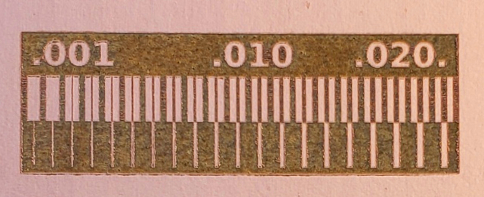
- characterize the design rules for your PCB production process, i.e. what is the useable minimum tracewidth for your PCB production process?
- Group Assignment Example
- individual assignment:
-
make an in-circuit programmer by milling and stuffing the PCB,
-
test it
-
ISP Programmer Example
- Download firmware
- Windows Toolchain installation
- Install git
- Install Atmel GNU toolchain
- Install GNU Make
- Install avrdude
- Update PATH environment variable
- Install driver (libusb-win32) for your programmer
- Sanity Check
- Start Git Bash and open terminal window
- Type make -v and press Enter
- Type avr-gcc –version and press Enter
- Type avrdude and press Enter
- Uploading firmware to ISP programmer
- Compiling firmware
- Unzip downloaded firmware to folder
- Open Makefile in text editor. Update MCU = attiny45 line to the correct MCU (e.g. attiny85). Save and exit.
- Open a terminal window and navigate to the firmware folder.
- Type make and press Enter. You should see the compiled firmware, fts_firmware.hex
- Connect working ISP programmer to your blank ISP programmer
- Upload firmware to your ISP programmer
- Type make flash and press Enter to upload the fts_firmware.hex file to your ISP programmer.
- Type make fuses and press Enter to program the fuse settings on the MCU.
- Check that Windows recognizes your ISP programmer
- Disconnect your ISP programmer board and plug it into a USB port on your notebook.
- Open Device Manager and check if Windows recognizes your ISP programmer. It should appear as USBtinySPI
- Disable the reset fuse on the MCU
- Reconnect the programming cable to your ISP programmer for the final step (disable reset pin, make it an I/O pin)
- Type make rstdisbl and press Enter
- Congratulations. You have uploaded the ISP firmware to your programmer.
- Check that you have the correct Windows driver
- Plug your ISP programmer to a USB port on your notebook
- Open Device Manager. Your programmer should appear under the libusb-win32 device as USBtinySPI
- Compiling firmware
- Refer to YeoGS assignment in the link below if you are unsure of the steps.
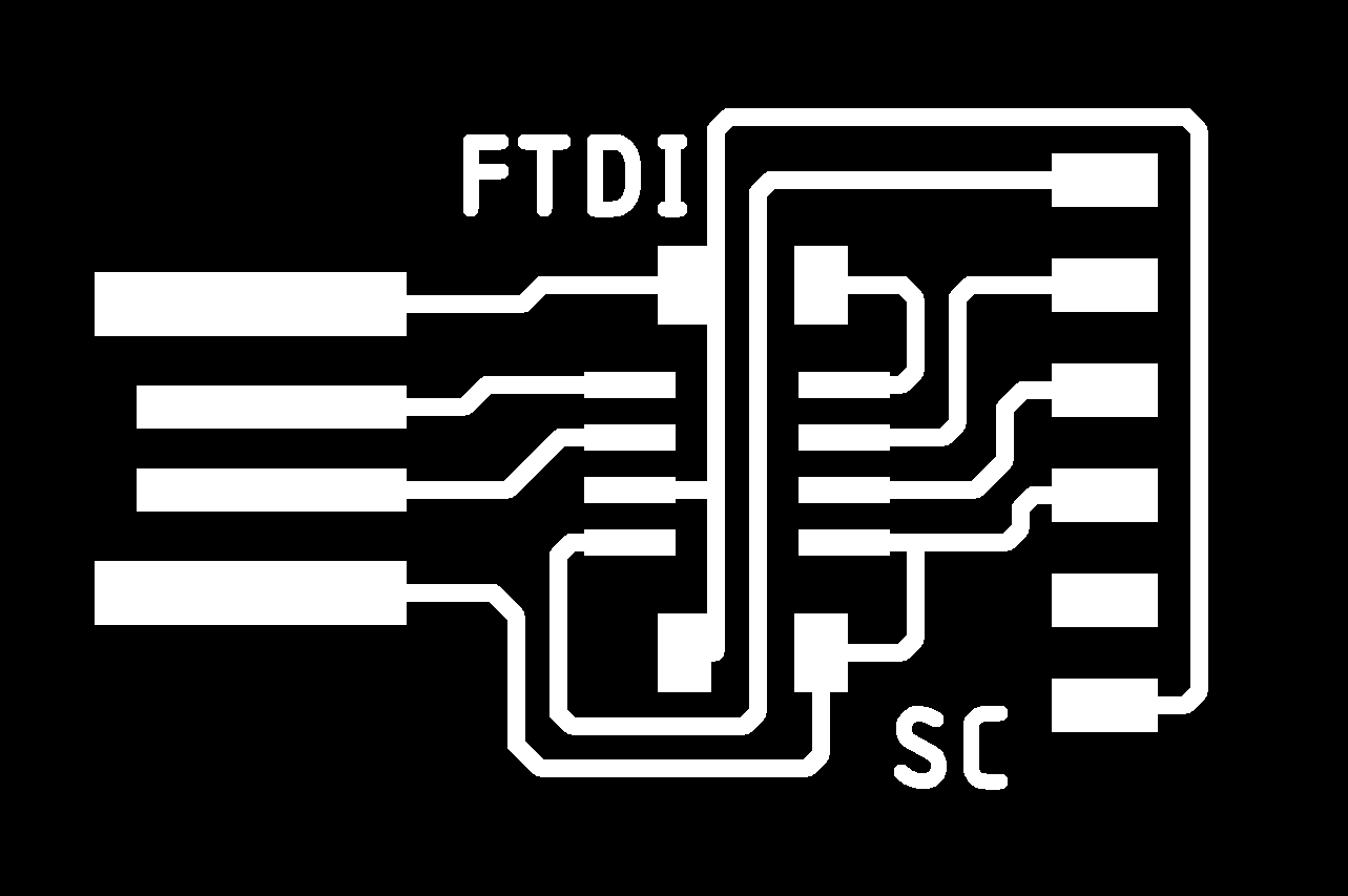
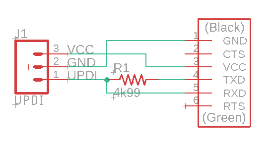
FTDI/UPDI Example
-
FTDI example: board components trace outline
-
FTDI-to-UDPI interface board: board components trace outline
ATSAMD11C Collection
Arduino ISP
Recommended settings for Stepcraft
| Operation | Endmill size | Cut Speed | Cut Depth | Total Depth | Offset |
|---|---|---|---|---|---|
| Traces | 0.4 mm flat | 50 ~ 60 mm/min | 0.04 ~ 0.05 mm | 0.04 ~ 0.05 mm | 2 ~ 4 |
| Traces | 0.8 mm flat | 60 ~ 80 mm/min | 0.04 ~ 0.05 mm | 0.04 ~ 0.05 mm | 1 ~ 2 |
| Traces | 0.1 mm 30 deg V-bit | 50 ~ 60 mm/min | 0.04 ~ 0.05 mm | 0.04 ~ 0.05 mm | 1 ~ 2 |
| Board Outline | 0.8 mm flat | 50 ~ 80 mm/min | 0.42 ~ 0.45 mm | 1.65 ~ 1.70 mm | 1 |
Note:
- Safety glasses must be used when viewing milling process
- confirm feedrate settings in G-code
- confirm z-sensor probe is activated when switch depressed
- perform an air cut or camotics simulation before beginning cutting
- perform z-calibration everyting endmill or mill bit is changed